The Role of Control Valves in Thermal Power Generation
In its Electricity 2024 report, the International Electricity Agency (IEA) predicted that data centers’ electricity demand could exceed 1,000 terawatt-hours (TWh) in 2026. That’s roughly the amount of electricity Japan consumes each year. Artificial intelligence (AI) is a driving factor for this surge in electricity usage, and it shows no signs of peaking yet.
The challenge, then, is meeting this increasing demand in the power generation industry. While global capacity for power generation from renewable sources grew by 50% year-on-year in 2023, overall electricity demand still outstrips that supply. So, conventional (fuel-burning) thermal power generation plants remain an essential part of the system that supports our accelerating technological frontiers.
Control valves keep critical processes flowing in thermal power generation. But they also help ensure overall system efficiency, maximizing output when we need it most. If you’re curious about the thermal power generation process and the pivotal role that control valves play, read on.
What is thermal power generation?
At a basic level, thermal power generation plants burn fuel to create physical energy. This physical energy spins a turbine, which turns a generator that produces electricity.
Conventional power plants (which don’t use renewable energy sources such as wind or solar) generally fall into three classifications. These are:
- Nuclear: Heats water via a controlled fusion reaction using uranium to create steam power.
- Biomass: Burns biological matter from living or recently-living materials, such as switchgrass, solid organic waste, or wood.
- Fossil: Burns fossil fuels, such as coal, natural gas, or crude oil.
Processes at conventional thermal power plants tend to be similar, regardless of fuel type, but for this article, we will focus on fossil thermal power generation.
The information above represents a simplified view of thermal power generation plants. In reality, they’re inherently complex, using multiple systems that need precise synchronization for the process to work. This is where control valves come in.
Control valves in thermal power generation
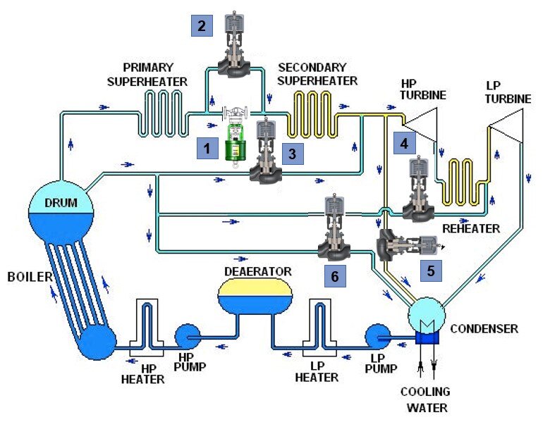
Three key systems rely on control valves for the thermal power generation process—the condensate system, the feedwater system, and the main steam system.
Combined with the boiler, these systems create, channel, and recycle steam which powers the electricity-generating turbines at the thermal power plant.
Feedwater system control valves
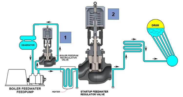
The feedwater system provides the boiler with the right volume of water at the right pressure and temperature. Usually, this equates to feedwater reaching the boiler at approximately 2400-3200 PSIG and 300-500°F.

The feedwater system has three main components. These are:
- Low and high-pressure feedwater heaters: Pre-heats the feedwater before it enters the boiler.
- Deaerator: Removes gases such as oxygen from the boiler feedwater.
- Boiler feedpump: Feeds the boiler the amount of water it needs to replace the water it uses to generate steam.
There are also two common control issues in feedwater systems. These are:
- Low flow: Insufficient flow to the boiler can lead to the tubes overheating.
- High flow: Excessive flow can lead to ‘wet’ steam entering the turbine. Wet steam can lead to issues such as water droplet erosion of the turbine blades, which decreases their efficiency and lifespan.
There are two control valves that play a crucial role in managing flow rate in the feedwater system.
The startup feedwater regulator valve is typically located after the high-pressure heater to control steam extracted from various stages of the turbine. This raises the temperature of the boiler.
The boiler feedpump recirculation valve is one of the most challenging applications in a power plant. It must function as both an on/off and modulating valve, which is a true test of its engineering. It also has to deal with cavitation. That’s why Trimteck always includes its multi-stage ST-2 or ST-4 cavitation trims and CVD-5B hardening in boiler feedpump recirculation valve design.
Main steam system control valves
The main steam system refers to the part of the plant that transports steam from the boiler to the high-pressure turbine.
First, the main steam system draws steam from the boiler and sends it through superheaters. These devices convert saturated (or ‘wet’) steam into superheated (or ‘dry’) steam. Superheated steam doesn’t carry the same risk of turbine damage as superheated steam. It’s also more thermally efficient—it doesn’t lose energy to the same extent as saturated steam does as it hits the turbines.
After superheating, the steam enters the high-pressure turbine. Then it’s sent through a reheater to increase its temperature (and its thermal efficiency) before it passes through the low-pressure turbine.
After the plant has extracted all the potential energy from the steam, it starts its ‘recycling’ journey in the condensate system.

Supporting the main steam system components are four different types of control valves. These are:
- Superheater valves: Maintain boiler pressure below 70% and modulate pressure to the turbine.
- Main steam attemperator valve: Controls high-pressure turbine temperature at 15% load.
- Reheater attemperator valve: controls low-pressure turbine temperature at 15% load.
- Bypass valves: Provides emergency steam redirection and helps manage excess steam load, temperature, and pressure for the turbine and superheater.
The greatest challenge for main steam system control valves is the recent emphasis on planned cycling as electricity demand fluctuates. This means frequent boiler start-ups, shutdowns, and varying system loads, which can be difficult to design for. Tackling this operational approach with control valves requires bespoke control valve solutions, like those Trimteck designed for Abengoa and Florida Power & Light.
There are also specialized valves that we precision-engineer at Trimteck to drive efficiency at thermal power generation plants.
Sootblower header control valves
The sootblower is a system that removes soot from the boiler’s surface by blowing hot steam or compressed air. If left to build up, surface soot reduces a boiler’s efficiency.
The sootblower header distributes air or steam across the boiler through multiple channels. To control the air or steam pressure in the sootblower header, you need a regulating (modulating valve. As the sootblower channels open and close, the header control valve must respond quickly to avoid pressure surges that would set off safety controls. As a result, the sootblower header control valve needs Class V shutoff to prevent any leakage that would increase header pressure.
Attemperator spray control valves
These valves control the amount of water required to control the steam temperature as it exits the superheaters.
The main steam attemperator spray control valve only needs to handle relatively low pressure drops, but it needs high rangeability. Conversely, the reheat attemperator spray control valve needs to tackle significantly higher pressure drops.
Desuperheaters
These valves work with the attemperator valve, also known as the cooling water valve. Together, they lower the temperature of superheated steam.
An efficient and well-designed desuperheater can inject a pre-set amount of water into the steam flow and maintain a temperature of 10°F over the steam saturation temperature. Modern desuperheater valve designs can precisely control even high-velocity water flow, overcoming the effects of cavitation, to deliver a controlled and atomized water spray.
Condensate system control valves
In this setting, condensate is steam that has cooled and condensed into water.
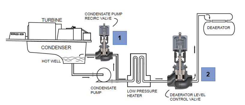
The condensate pump draws condensate from the condenser hot well, a storage reservoir attached to the condenser. The condenser cools and condenses steam after it has been through the turbines so the system can reuse it, increasing its efficiency. The condensate system then circulates the condensate through low-pressure heaters and to the deaerator, which removes impurities rom the boiler feedwater. These include carbon dioxide, iron, and copper.
The condenser acts as a heat exchanger with a dual purpose. It creates a vacuum, which increases the turbine’s efficiency. It also recovers quality feedwater (condensate) after it has passed through the turbines.

There are two common control issues in condensate systems. These are:
- Minimum flow requirement: The condensate pump needs constant minimum flow to prevent overheating and protect it from cavitation.
- Water quality: “Blows down” dissolved and suspended impurities in the condensate.
Two control valves help the condensate system to function:
The condensate pump recirculation valve allows additional flow through the pump as the system requires it. Outlet pressure from the pump ranges from 300 to 600psi at temperatures from 100-150°F. It also faces cavitation and must have a positive shutoff in the form of a soft valve seat.
The deareator level control valve maintains a level in the deareator. It must have high rangeability, cavitation protection at low flows, and low resistance at increasing flows. These aren’t easy to achieve with off-the-shelf control valves. But custom control valves, like those we precision-engineer at Trimteck, can factor all of a system’s unique requirements into the design.
Enhancing power generation system performance
If you’re a thermal power generation plant engineer or technician, you’ll be all too familiar with the impact that cycling and spiking electricity demand is having on your process control systems. Standard solutions struggle to stand up to these new challenges. That’s why you need rugged, reliable, and precision-engineered control valves.
At Trimteck, our Application Engineers review the unique specifications and conditions of every quote request to identify a bespoke solution that will help you drive performance. To get started, visit our Quote Center.


